
HIPIMS Power Supply Configuration for Laboratory-Scale Thin Film Deposition
General Technical Support Guide
1. Purpose and Scope
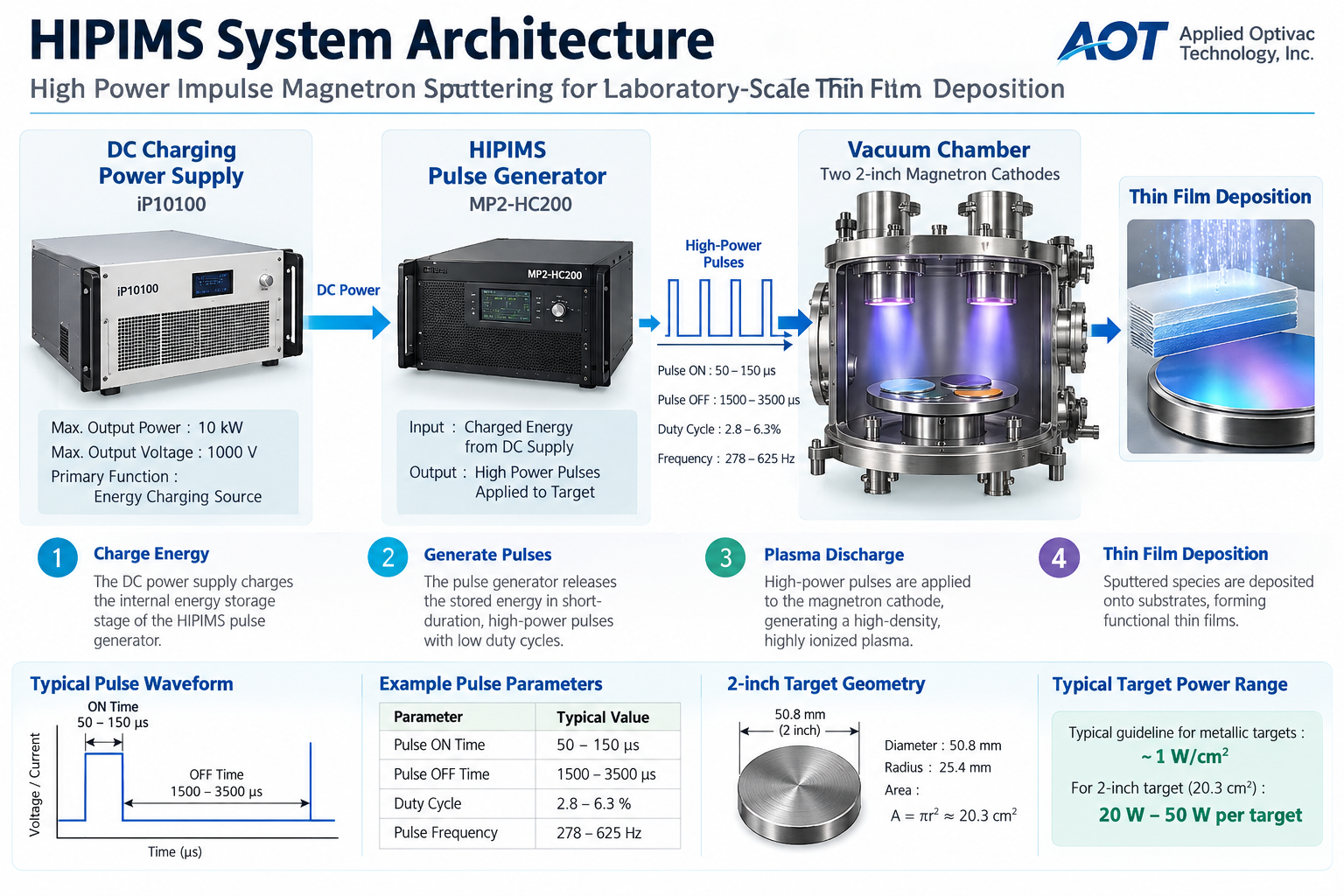
This guide introduces a representative power-supply architecture for laboratory-scale High Power Impulse Magnetron Sputtering (HIPIMS). It explains the roles of a DC charging supply and a HIPIMS pulse generator, summarizes example pulse calculations, and provides a checklist for preliminary system evaluation.
2. Representative Laboratory Configuration
The following values describe one example configuration. They should not be interpreted as universal requirements for HIPIMS equipment.
| Item | Example configuration |
|---|---|
| Vacuum chamber | Ø250 mm × 300 mm |
| Substrate holder | Ø80 mm |
| Magnetron cathodes | Two 2-inch cathodes |
| Initial target materials | Copper (Cu) and titanium (Ti) |
| Possible research extensions | TiN, TiO₂, SiO₂, Si₃N₄ and other functional films, where the target, gas delivery and process controls are suitable |
| DC charging supply example | iP10100; maximum output power 10 kW; maximum output voltage 1000 V |
| HIPIMS pulse generator example | MP2-HC200 |
Confirm model specifications, electrical interfaces, operating limits and approved combinations with the equipment manufacturers before integration.
3. System Architecture
In this architecture, the DC supply provides energy to charge the pulse generator’s energy-storage stage. The pulse generator delivers controlled, short-duration high-power pulses to the cathode.
The DC supply’s nameplate rating is not, by itself, the continuous power applied to the target. Target peak power, average power and energy per pulse depend on the pulse generator, settings, load and component limits.
4. HIPIMS Operating Principle
Conventional DC sputtering applies power continuously. HIPIMS instead accumulates energy and releases it in short, high-power pulses. This operating mode can generate a highly ionized plasma; peak pulse conditions and average thermal loading are distinct quantities.
- Energy is supplied by the DC power source.
- Energy is accumulated in the pulse generator’s energy-storage stage.
- Stored energy is released as a short pulse.
- A high-density plasma is generated near the target.
- The system returns to its charging phase before the next pulse.
5. Example Pulse Parameters and Calculations
| Parameter | Illustrative value |
|---|---|
| Pulse ON time | 100 μs |
| Pulse OFF time | 1500–3500 μs |
| Duty cycle | Approximately 2.8–6.3% |
| Pulse repetition frequency | Approximately 278–625 Hz |
For 100 μs ON and 1500 μs OFF, the duty cycle is approximately 6.25% and the repetition frequency is approximately 625 Hz. For 100 μs ON and 3500 μs OFF, the duty cycle is approximately 2.78% and the repetition frequency is approximately 278 Hz.
These are calculation examples, not recommended settings for every system. Verify pulse width, repetition rate, peak current, energy per pulse and average power against the specific generator, cathode, load and process limits.
6. Preliminary Target-Area Estimate
For a nominal 2-inch target, diameter = 50.8 mm and radius = 25.4 mm. The nominal circular face area is:
At a reference value of 1 W/cm², this area corresponds to approximately 20 W. A 20–50 W-per-target range may be useful as a rough starting reference in some conventional sputtering discussions, but it is not a validated HIPIMS setpoint or universal operating limit.
HIPIMS evaluation must consider peak power and current density as well as average power. Establish actual conditions using the target and cathode ratings, pulse-generator limits, cooling capacity, process objectives and validated procedures.
7. How to Interpret a 10 kW DC Supply
A 10 kW DC supply may appear oversized when compared with a small target’s average power. In a pulse-generator architecture, however, the DC supply’s rating describes its charging capability; it does not independently determine the power delivered to the target during each pulse.
Review the charging voltage/current range, pulse-generator input requirements, energy-storage limits, repetition rate, load compatibility, thermal management, grounding, interlocks and protective functions. Confirm that the selected components are specified to operate together.
8. Potential Research Applications
- Copper and titanium thin-film deposition studies
- Process-parameter optimization
- Plasma diagnostics and discharge characterization
- Film density and film-property evaluation
- Reactive deposition studies for nitride or oxide films, where suitably configured
- Optical interference coatings and other functional thin films
Achievable film properties depend on the complete process, including target and substrate materials, chamber pressure, gas composition and flow, substrate bias and temperature, target-to-substrate geometry, pulse conditions and other process variables.
9. Preliminary System Review Checklist
- Verify current model specifications and electrical/interface requirements for both power units.
- Confirm charging voltage and current compatibility, pulse-energy limits and repetition-rate limits.
- Check target and cathode ratings, cooling, cables, connectors and grounding.
- Review vacuum and gas-delivery systems, including reactive-process controls where applicable.
- Confirm interlocks, over-current/over-voltage protection and emergency shutdown arrangements.
- Agree on commissioning tests and operating limits with the equipment suppliers before process use.
10. Technical Assessment and Conclusion
A DC charging supply paired with a dedicated HIPIMS pulse generator is a coherent architecture for laboratory-scale pulsed magnetron sputtering when the selected components are properly matched. The DC supply charges the pulse generator, and the pulse generator controls the pulses delivered to the cathode.
For the example described in this guide, the proposed architecture uses an iP10100 DC supply and an MP2-HC200 pulse generator. Final suitability must be established through current model-specific documentation, interface checks, load and thermal evaluation, and safe commissioning. This guide is a starting point for technical discussion, not a blanket certification of compatibility.