
Integrating Multiple DC Power Supplies with a Pulse Power Unit
Two general connection approaches for integrating multiple DC power supplies with a pulse power unit: an interface-based architecture using a DC combiner, and a cable-based architecture using a multi-branch cable assembly.
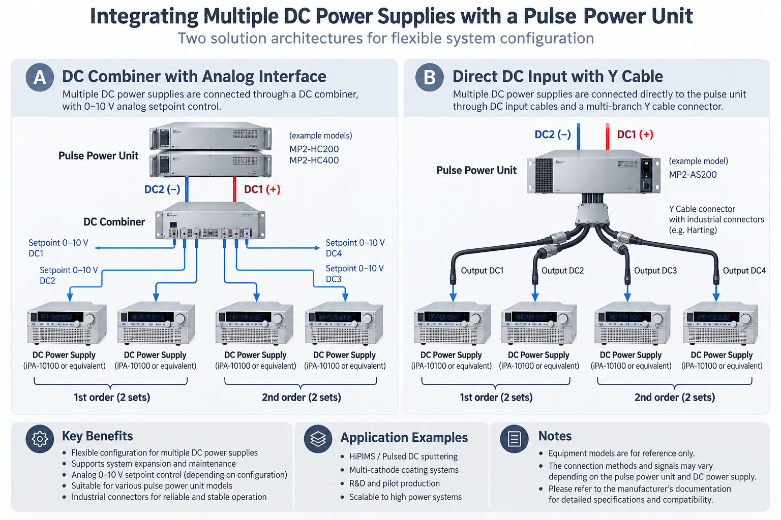
01 · Architecture A — Interface and DC Combiner
Each DC power supply connects through a defined control/interface connection to a DC combiner. The combiner provides the system-level connection to the pulse power unit. The reference configuration showed four DC supplies and four individual 0–10 V DC setpoint labels.
Conceptual illustration only. Confirm signal path, power path, polarity, and connector assignment from equipment documentation.
Potential characteristics
- A dedicated combiner serves as the defined integration point.
- Individual control/setpoint channels may be identified at system level.
- The architecture can be documented and inspected as a distinct subsystem.
Items to confirm
- Interface type and pin assignment.
- Setpoint range, reference potential, and isolation requirements.
- Permitted number and configuration of connected supplies.
02 · Architecture B — DC Input Cable and Multi-Branch Connector
DC input cables connect the power supplies to the pulse power unit through a multi-branch cable assembly. The reference configuration used a Y-cable concept with industrial multipole connectors and four output labels.
Conceptual illustration only. Specify the actual cable topology, connector model, and pin assignments for each system.
Potential characteristics
- Uses a dedicated cable assembly as the interconnection element.
- May simplify the visible system layout when well documented.
- Requires precise control of cable construction and connector pinout.
Items to confirm
- Connector part numbers and contact assignments.
- Current and voltage ratings for each conductor and connector.
- Cable length, conductor size, grounding, shielding, and strain relief as applicable.
03 · Architecture Comparison
| Consideration | Interface / DC combiner | Multi-branch cable assembly |
|---|---|---|
| Integration element | Dedicated DC combiner and defined interface | DC cables and multi-branch connector assembly |
| Control / channel identification | May include individual setpoint or interface channels | Defined by approved cable wiring and channel mapping |
| Main documentation need | Interface specification, combiner documentation, system diagram | Cable drawing, connector pinout, conductor ratings, channel map |
| Selection basis | Compatibility and the combiner’s specified function | Compatibility and cable assembly electrical/mechanical ratings |
Neither approach is universally preferable. Selection depends on manufacturer-approved configuration, electrical ratings, control requirements, maintainability, and intended operating conditions.
04 · Engineering Verification Checklist
- Confirm exact models and manufacturer-approved compatibility of all power supplies, combiner/interface hardware, and pulse unit.
- Verify output voltage/current ratings, polarity, grounding, isolation, and restrictions on connecting multiple supplies.
- Document the distinction between control/setpoint wiring and the DC power path.
- Verify connector part numbers, pin assignments, current capacity, cable construction, and strain relief.
- Define each channel and any installation group/stage label; do not infer this from a conceptual drawing.
- Review protection, interlocks, emergency-stop behavior, and safe energization procedures against manuals and site requirements.
- Release an approved wiring diagram and bill of materials before implementation.
Generalized from a prior multi-DC-power-supply integration proposal. Actual implementation details must be established for each system.