
Preliminary HIPIMS Power Supply Sizing Guide
For Large-Area Copper Targets with a Moving Magnet Assembly
1. Objective
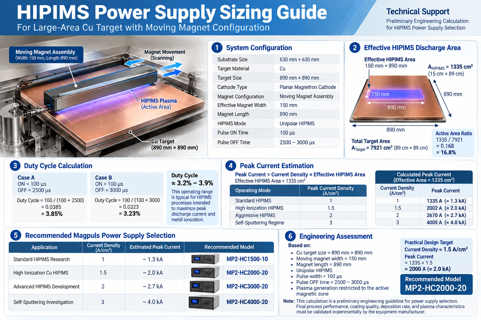
This guide presents a preliminary method for estimating the required peak pulse current and selecting a suitable HIPIMS power supply for a large-area copper (Cu) cathode using a moving magnet assembly.
It is intended as an initial engineering guideline for equipment design and power-supply selection. Actual process performance, coating quality, deposition rate, and plasma characteristics must be validated on the specific coating system.
2. Example System Configuration
| Parameter | Example specification |
|---|---|
| Substrate size | 630 mm x 630 mm |
| Target material | Copper (Cu) |
| Target size | 890 mm x 890 mm |
| Cathode type | Planar magnetron cathode |
| Magnet configuration | Moving magnet assembly |
| Effective magnet width | 150 mm |
| Magnet length | 890 mm |
| HIPIMS mode | Unipolar HIPIMS |
| Pulse ON time | 100 microseconds |
| Pulse OFF time | 2,500-3,000 microseconds |
3. Effective HIPIMS Discharge Area
For this example, the active discharge region is assumed to be the area directly above the moving magnetic field. This is an engineering assumption and must be confirmed against the actual magnetic-field and cathode configuration.
Under this assumption, approximately 16.8% of the target area is active in the discharge zone at a given moment. The plasma zone moves as the magnet assembly scans.
4. Duty Cycle Calculation
Case A: ON time = 100 microseconds; OFF time = 2,500 microseconds.
Case B: ON time = 100 microseconds; OFF time = 3,000 microseconds.
The example duty-cycle range is therefore approximately 3.2%-3.9%. The suitable operating range depends on the intended process window and the capabilities of the complete system.
5. Peak Current Estimation
A first-order estimate of peak current can be made by multiplying the assumed peak current density by the effective discharge area.
| Illustrative operating mode | Assumed current density | Estimated peak current |
|---|---|---|
| Standard HIPIMS | 1 A/cm^2 | 1,335 A (about 1.3 kA) |
| High-ionization HIPIMS | 1.5 A/cm^2 | 2,002 A (about 2.0 kA) |
| Advanced HIPIMS development | 2 A/cm^2 | 2,670 A (about 2.7 kA) |
| Self-sputtering investigation | 3 A/cm^2 | 4,005 A (about 4.0 kA) |
These current-density values are illustrative sizing assumptions, not guaranteed operating points. The achievable peak current depends on the power supply, cathode impedance, pulse waveform, magnetic field, and process conditions.
6. Illustrative Power Supply Selection
The following model mapping is an example based on one power-supply product range. Confirm current product availability, ratings, compatibility, and operating limits with the relevant manufacturer before specifying equipment.
| Application | Estimated peak current | Example model |
|---|---|---|
| Standard HIPIMS research | About 1.3 kA | MP2-HC1500-10 |
| High-ionization Cu HIPIMS | About 2.0 kA | MP2-HC2000-20 |
| Advanced HIPIMS development | About 2.7 kA | MP2-HC3000-20 |
| Self-sputtering investigation | About 4.0 kA | MP2-HC4000-20 |
For the example configuration, a design point near 1.5 A/cm^2 gives an estimated peak current of approximately 2.0 kA. A supply rated for that operating region may be a reasonable starting point for technical evaluation, subject to manufacturer confirmation and system testing.
7. Engineering Considerations
The example estimate is based on a 890 mm x 890 mm Cu target, a 150 mm x 890 mm active magnetic zone, unipolar HIPIMS, a 100-microsecond pulse ON time, and a 2,500-3,000-microsecond pulse OFF time.
A moving-plasma configuration may offer potential benefits such as improved target utilization, reduced localized heating, less concentrated erosion tracks, and improved large-area process scalability. These outcomes are design-dependent and should be verified experimentally.
Before final selection, review the magnetic-field distribution, cathode geometry, target thickness, working pressure, gas composition, substrate bias, pulse waveform, required deposition rate, and target film properties.
8. Validation and Disclaimer
This document is a preliminary engineering sizing guide only. It is not a guarantee of process performance, coating quality, deposition rate, or suitability for a particular machine.
Final power-supply selection and process optimization should be performed with the equipment manufacturer using the actual cathode, magnet assembly, electrical configuration, and coating process. All example values and model references must be checked against current manufacturer specifications.